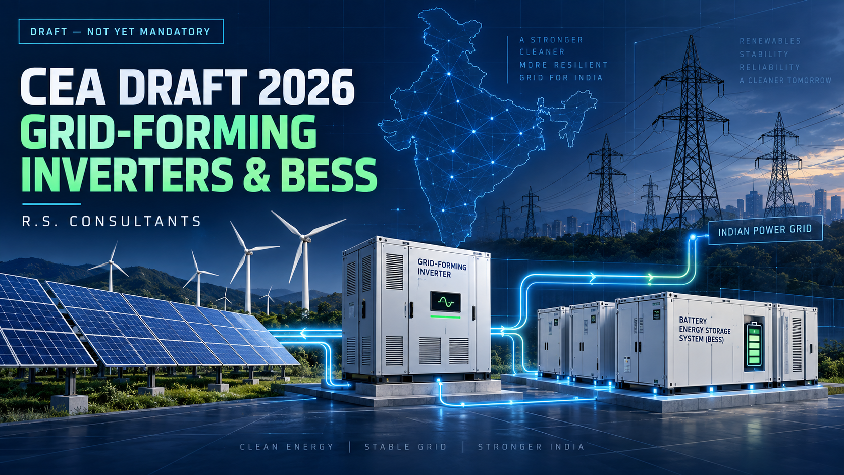
CEA’s Proposed Grid-Forming Inverter and Energy Storage Requirements: Key Design Implications
India’s electrical grid is undergoing a significant transformation as renewable-energy capacity continues to increase. Unlike conventional synchronous generators, most solar and wind plants connect to the grid through power-electronic inverters. This changing generation mix creates new challenges involving grid stability, voltage control, frequency response and system resilience.
To address these concerns, the Central Electricity Authority (CEA) published the Draft Central Electricity Authority (Technical Standards for Construction of Electric Plants and Electric Lines) Second Amendment Regulations, 2026 on 3 September 2026.
The draft proposes important requirements concerning grid-forming inverters and co-located energy-storage systems for renewable-energy plants commissioned after specified dates.
It is important to emphasise that these provisions are currently draft proposals and are not yet enforceable requirements.
What Has the CEA Proposed?
According to the draft amendment, renewable-energy power plants commissioned after 1 July 2027 would be required to provide:
- Grid-forming control in at least 15% of the plant’s inverters.
- Grid-forming control in every power conversion system, or PCS, associated with a battery energy storage system.
- Co-located energy storage for applicable ground-mounted solar and onshore wind projects.
The proposed storage capacity for ground-mounted solar and onshore wind plants is:
- At least 10% of the plant’s installed power capacity.
- A minimum storage duration of two hours for plants commissioned after 1 July 2027.
- A minimum storage duration of four hours for plants commissioned from 1 July 2029 to 30 June 2031.
For example, under the proposal, a 100 MW solar power plant commissioned after 1 July 2027 would require a minimum co-located storage system of:
Storage power capacity = 10% × 100 MW = 10 MW
Storage energy capacity = 10 MW × 2 hours = 20 MWh
For the later four-hour requirement, the corresponding storage capacity would become:
10 MW × 4 hours = 40 MWh
The complete proposal is available in the CEA draft notification dated 3 September 2026.
What Is a Grid-Forming Inverter?
Most conventional renewable-energy inverters operate in grid-following mode. These inverters detect the voltage and frequency already present on the grid and synchronise their output accordingly.
A grid-forming inverter performs a more active role. It can establish and regulate a voltage and frequency reference, allowing it to support the power system during disturbances or when the grid has limited synchronous generation.
In simplified terms:
- A grid-following inverter follows an existing electrical waveform.
- A grid-forming inverter helps establish and stabilise that waveform.
Grid-forming technology can contribute to voltage stability, frequency control, system-strength improvement and the reliable operation of renewable-heavy electrical networks.
However, merely mentioning “grid-forming capability” in a specification is insufficient. The required operating modes, response characteristics, control philosophy, testing procedures and interaction with the wider network must be defined and verified.
Why Is Energy Storage Being Linked With Renewable Generation?
Solar and wind generation are variable by nature. Their output depends on solar irradiance, weather conditions and wind availability, rather than only on electricity demand.
Co-located battery energy storage can help manage this variability by:
- Absorbing excess renewable generation.
- Supporting the grid during rapid generation changes.
- Providing active and reactive power response.
- Improving ramp-rate control.
- Assisting frequency and voltage regulation.
- Reducing renewable-energy curtailment.
- Supporting controlled power delivery during peak-demand periods.
The proposed CEA requirements therefore indicate a movement away from evaluating renewable plants only by their installed MW capacity. Future projects may increasingly be evaluated as integrated systems comprising generation, storage, controls, protection and grid-support functions.
Practical Implications for Electrical Designers
Although the proposal primarily concerns utility-scale renewable-energy plants, it may also influence large developments incorporating captive solar plants, battery storage or grid-connected renewable infrastructure.
These may include data centres, industrial facilities, institutional campuses, airports, large commercial developments and mixed-use townships.
1. Inverter and PCS specifications
Specifications may need to define grid-forming functionality rather than referring only to inverter efficiency, power factor and basic grid compliance.
The design documentation should identify:
- Required grid-forming capacity.
- Applicable operating modes.
- Active and reactive power capabilities.
- Voltage and frequency response.
- Black-start or islanding requirements, where applicable.
- Communication and supervisory-control interfaces.
- Compliance-testing and performance-verification procedures.
2. Battery sizing
A basic MW/MWh calculation is only the starting point. Designers should also consider:
- Battery degradation over the project life.
- Depth-of-discharge limits.
- Round-trip efficiency.
- Auxiliary-system consumption.
- Operating reserve.
- Ambient-temperature effects.
- Future augmentation requirements.
- Charging and discharging cycles.
The battery installed on the commissioning date may need additional capacity to maintain the contracted performance over its intended service life.
3. Transformer, switchgear and cable selection
Battery systems create bidirectional power flow. Transformers, busbars, switchgear and cables must therefore be assessed for both charging and discharging conditions.
The analysis should include:
- Maximum continuous current.
- Overload and emergency operating conditions.
- Harmonic contribution.
- Voltage variation.
- Short-circuit contribution from inverter-based resources.
- Cable derating and installation conditions.
- Transformer losses and loading profile.
- Switching duties and equipment ratings.
4. Protection coordination
Inverter-based resources do not necessarily behave like conventional rotating generators during faults. Their fault-current magnitude, duration and control response can differ substantially.
Protection design may consequently require:
- Detailed inverter fault-current data from manufacturers.
- Directional protection where bidirectional current flow is possible.
- Revised relay settings.
- Anti-islanding protection.
- Coordination between inverter, BESS and utility protection.
- Verification under grid-connected and islanded operating modes.
- Dynamic simulation where required by the grid authority.
Protection settings should not be based solely on assumptions taken from conventional generator studies.
5. Earthing and bonding
A combined solar-and-storage installation requires coordinated earthing across multiple systems, including PV structures, inverter stations, battery enclosures, transformers, switchgear, cable screens and communication equipment.
Designers should assess:
- Touch and step potential.
- Equipment bonding.
- Neutral-earthing philosophy.
- Earthing under islanded operation.
- Lightning and surge protection.
- Electromagnetic compatibility.
- Integration with the site’s principal earthing network.
Particular attention is required when system operating modes change the location or availability of the neutral reference.
6. Space planning and fire safety
Energy storage is not simply an electrical-equipment addition. It affects architectural planning, structural coordination, ventilation, fire protection, access and emergency response.
Early-stage coordination should address:
- BESS location and separation.
- Fire detection and suppression strategy.
- Ventilation and thermal management.
- Emergency isolation.
- Maintenance and replacement access.
- Drainage and environmental conditions.
- Fire-service access and emergency signage.
- Applicable battery and fire-safety standards.
Late inclusion of BESS can create serious problems involving space, cable routing, equipment clearances and project approvals.
Implications for MEP Coordination
The proposed regulations demonstrate why renewable-energy and storage systems cannot be designed in isolation.
A successful project requires clear coordination among:
- The electrical and MEP consultant.
- Renewable-energy designers.
- BESS specialists.
- EPC contractors.
- Inverter and PCS manufacturers.
- Fire and life-safety consultants.
- Structural and architectural teams.
- The distribution licensee or grid authority.
The project responsibility matrix should identify who is responsible for grid studies, protection coordination, dynamic modelling, equipment integration, fire strategy, testing and final compliance.
Should Current Projects Adopt These Requirements?
The draft should not automatically be treated as a mandatory provision because it has not yet become enforceable.
Nevertheless, projects with commissioning dates extending beyond July 2027 should review the proposal during the design stage. Ignoring a probable regulatory direction could lead to inadequate land allocation, undersized electrical infrastructure, incomplete specifications or expensive redesign later.
A practical approach is to:
- Record the proposal in the project’s regulatory-risk register.
- Assess whether the project falls within its intended scope.
- Reserve adequate space and electrical capacity where justified.
- Discuss future-compliance options with the client and utility.
- Update the design after the final regulation is notified.
- Avoid claiming statutory compliance until the final requirements are published.
Conclusion
The CEA’s draft amendment represents an important shift in renewable-energy design. The focus is moving from simple renewable-generation capacity toward systems capable of supporting grid stability through advanced inverter controls and energy storage.
For electrical consultants, this development reinforces the need to integrate renewable generation, BESS, protection, earthing, controls, fire safety and grid-compliance studies from the earliest stages of a project.
Future-ready electrical design will not be achieved merely by adding solar panels or batteries to an existing distribution scheme. It will require a coordinated system in which generation, storage, protection and control operate as one reliable electrical infrastructure.
Disclaimer: This article discusses draft regulations published for stakeholder consultation. Project-specific requirements should be confirmed using the final notified regulations, applicable Indian Standards, contractual requirements and directions issued by the relevant electrical or grid authority.